Unpack the controller
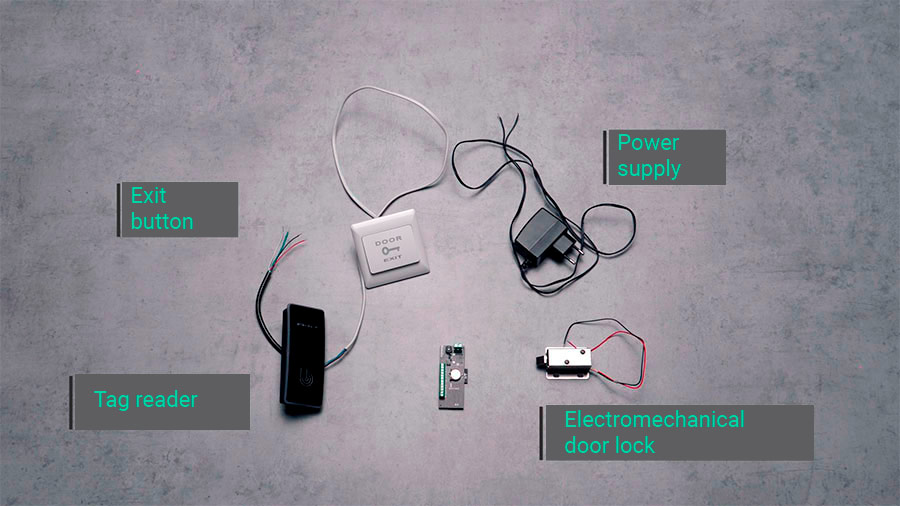
Open the packages containing the controller and other equipment that it will control. The standard set for the door includes an electromechanical lock, a tag reader, and an exit button – all of these must be purchased separately.
Connect equipment and power
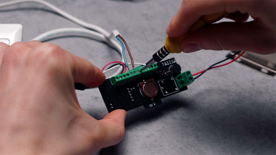
You will need a small flathead screwdriver and a wire stripper to connect the equipment.
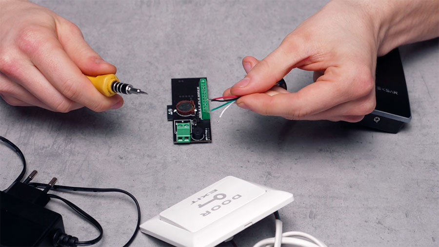
Reader connection
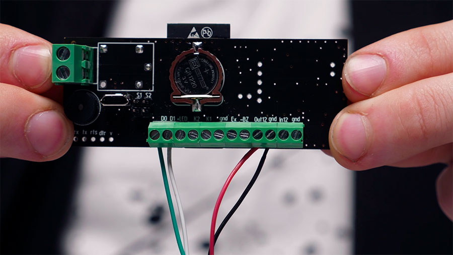
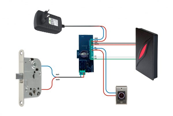
To connect the reader, you need to determine the purpose of each of the wires coming from it. They are usually marked with different colors according to the standard scheme:
- red – “+” 12 volt supply (“out12” or “reader power +” on the controller board);
- black – “-” 12 volt supply (“GND” on the board);
- green D0 and white D1 — to control the lock using the standard Wiegand protocol (“D0” and “D1” on the board).
Remove the insulation from the end of each of the wires, and loosen the clamping screws on the controller terminals. Insert the wires into their places according to the described scheme and tighten the clamping screws.
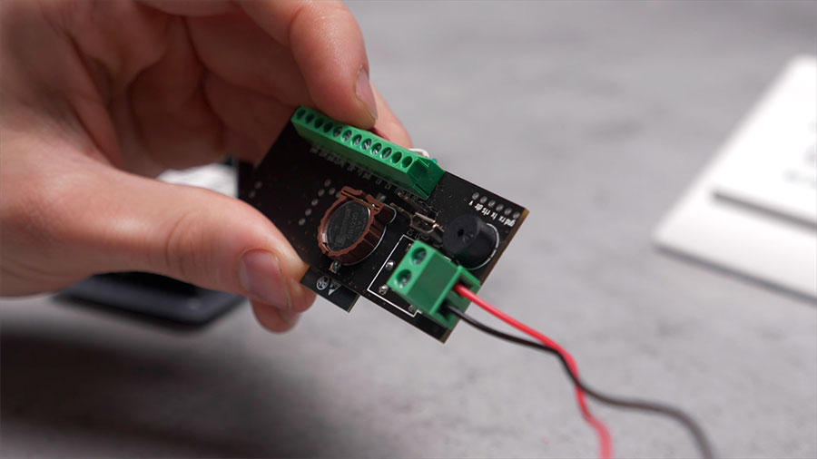
Lock or gate drive connection
To connect an electromechanical lock (electromagnetic lock, gate drive or barrier drive) to the controller, you need to determine the polarity of its power wires. Usually, red is a plus, and black or blue is a minus. If the wire colors are non-standard, find the marking on the case or check it in the device manual.
The power wires of the lock or drive are connected to the controller like the reader wires. To do this, use the terminals of the control output, located separately on the side of the board.
Exit button connection
When connecting the exit button, the polarity does not matter – you can connect the “plus” and “minus” of the power supply in any way. The button only closes the electrical circuit. Connect the button power wires to the controller – use the “Ex” terminal and the “GND” closest to it.
Power supply connection
After all devices are connected to the controller, you can connect it to a 12V power supply. Connect the “+” wire of the power supply to the “In 12” input and the “-” wire to the “GND” terminal.
Now your device is completely assembled. You can connect it to the free 2Smart Cloud mobile application or a cloud-based ACS.
The 2Smart Cloud mobile application is a variety of access control options for a home or small office. This option is for those who do not need access personalization when for all users, there are the same keys (instructions for connecting to 2Smart Cloud are here).
A cloud-based ACS with a paid subscription gives you maximum opportunities: convenient management of many users, scheduling access settings, personal access settings for each user, and grouping access points (instructions for connecting to a cloud-based ACS are here).
Reset controller settings
Use buttons S1 and S2 on the board to reset the settings and reboot the controller. There are two reset options:
- Press the S2 button and, without releasing it, briefly press and release S1. After 10 seconds, release S2.
- Turn off power to the board. Press the S2 button and, without releasing it, turn on the power. After 10 seconds, release S2.